
|
PLEASE PATRONIZE OUR SPONSORS!


|
|||||||
 |
|
|
Thread Tools | Display Modes |
|
|
|
#1
 01-08-2012, 01:28 AM
|
||||
|
||||
|
I happened to pull out a like new 4 terminal starter relay from a tractor carcass and thought I might whip together a small tutorial on one method of confirming the operation of the relay.
In the pics below, I substituted a modest battery charger for a 12 volt power source. In the first picture, an "overly simplified" multimeter is set to read the lowest OHMS range possible. The multimeter leads are then connected across the top "starter" studs of the relay. These studs will allow connection of the battery + cable to the starter + stud. The ohm meter will indicate if there is a conductive pathway from one top stud to the other. Also note the + cable from the battery is NOT connected to the signal tabs of the relay assembly. Note that no current is flowing thru the battery charger since the + lead is not yet connected to the relay. If the relay is functioning properly in this mode, the ohmmeter should indicate no electrical pathway exists thru the starter studs and the ohmmeter should indicate an infinite resistance. This is usually displayed as a ---- on most meter readouts. An analog meter will swing the needle to the infinity symbol on the meter face.  The 2nd diagnostic step will connect the + lead from the battery charger of the relay. Please note the negative battery lead is not connected to the relay frame but to the 2nd signal tab. A visual explanation of the 2nd tab will appear later in a x-ray view of the relay internals. Current should now be flowing through the solenoid relay inside the relay case. The battery charger should jump to about 2 amps of current if the relay coil is ELECTRICALLY intact. When the battery charger + cable is attached, a loud clack sound should also be heard / felt from the relay body. The clack sound would be the first clue the relay might be MECHANICALLY functional too. CLICKING DOES NOT GUARANTEE THE RELAY IS FUNCTIONAL FOR ITS INTENDED PURPOSE OF ENERGIZING THE STARTER MOTOR. Further, note the ohmmeter reading with the power applied to the relay assembly. If the "starter contacts" in the relay are ELECTRICALLY functional, the ohmmeter should change to a reading of near 0 ohms resistance. 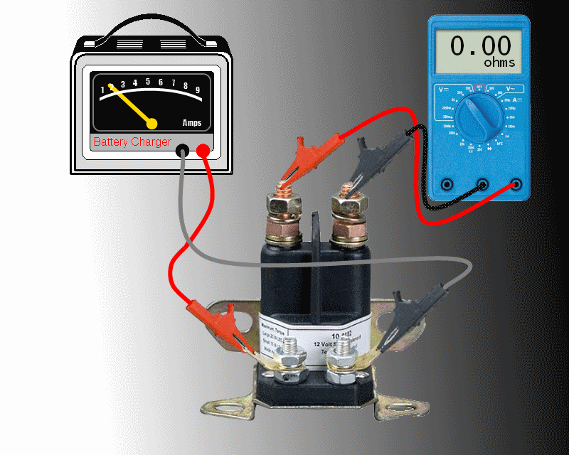 When near 0 ohms are confirmed, remove the + battery lead from the relay signal tab and another click should be heard, the ohmmeter reading should once again change to an infinite ohms reading (----). So what goes on inside the relay body? Here is a X-ray view of the internal workings. First picture is no power applied to the signal tabs and the starter relay studs are not bridged by the copper bar mounted to solenoid plunger. No electrical path should exist between the two top starter wiring studs. 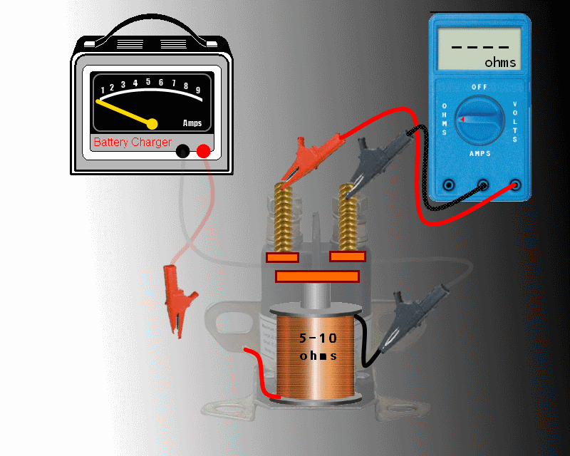 Apply the 12 volts from the battery charger, 2 amps current should flow through the relay coil. The current flow creates an electromagnet out of the relay coil. 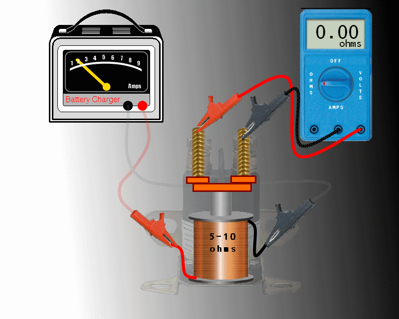 The magnetic field of the relay coil will repel the iron rod plunger out of the center of the coil. The plunger is forced to travel away from the body of the energized coil. Attached to the plunger is either a copper disc or a copper bar that will be forced up against the two top starter studs. This creates an electrical pathway through the top starter studs and allows current to flow from the battery to the starter motor. The only real difference between a 3 pole relay and a 4 pole relay is the electrical wiring to the additional signal tab. Instead of the negative wire from the relay coil going to the "2nd signal tab", the ground wire of the relay coil is spot welded to the metal frame of the relay body. The ground connection for a 3 pole relay is picked up through the mechanical bond of relay frame to tractor frame. In a 4 pole relay, the electrical connection is picked up through ground wiring to the negative signal tab. 
|
|
#2
01-08-2012, 01:31 AM
|
|||
|
|||
|
The only problem I see with your diagram is that, that is a solenoid and not a relay. But thanks for posting. That should be a big help.
AJ
__________________
1980 [COLOR="Red"][/COLOR]482- Stock 1981 [COLOR="Red"][/COLOR]582- Mag18, Sleeve Hitch, Spring assist 1979 [COLOR="Red"][/COLOR]682- Mag18, Sleeve Hitch, Spring Assist, #1 Tiller 1980 [COLOR="Red"][/COLOR]782- Mag18, Sleeve Hitch 1983 [COLOR="Red"][/COLOR]982- Stock, Fully Optioned
|
|
#3
01-08-2012, 05:49 AM
|
|||
|
|||
|
This is a singe pole N.O. Relay. Relays are nothing more than a solenoid, yoke, spanner bar, and contacts. Nice graphics!
__________________
"07" GT2554 Cub Triple Bagger Cub Roller Cub Sweeper Cub Blade Sears Dump Cart Sears spreader
|
|
#4
01-08-2012, 08:31 AM
|
|||
|
|||
 Solenoid.....Relay.....Contactor all terms that are used to describe the above device. Solenoid.....Relay.....Contactor all terms that are used to describe the above device. In researching this for my own interest, I have come to see the following...  "A relay is in essence a switch with two positions, on and off. A solenoid, meanwhile, enables mechanical components to physically move and change position, for example, a starter motor engaging a flywheel." Thus, the solenoid coil is part of the relay assembly. "And here is the definition from IEEE. Relay: A device by which contacts in one circuit are operated by a change in conditions in the same circuit or in one or more associated circuits. Contactor: A device for repeatedly establishing and interrupting an electric power circuit." I have to admit, that I have mixed the terminology around myself. But from the definitions that I have just discovered, I find that the proper term would be: Starter Contactor. In my line of work, I have always associated relays handling light electrical loads while a contactor handles heavy electrical loads but never knew the true definition. Looks like I learned something today. 
__________________
[B]Roland Bedell[/B] CC Models: 100, 105, 1450, 782, (2) 784, & 2072 [SIZE="4"][B][COLOR="Red"]Buy:[/COLOR][COLOR="Blue"] Made in the USA[/COLOR][/B] [/SIZE]:American Flag 1:
|
|
#5
01-08-2012, 10:18 AM
|
|||
|
|||
|
The IEEE defininations are correct. To expand upon them: A Relay is used on light electrical loads (usually 10 amps or less) and used in control circuits not Motor circuits. A Contactor is used to switch higher loads (10+ amps) both Horsepower and Resistive loads and a Starter Contactor is a Horsepower rated device for Motor loads and is usually mated with a Overload Relay to protect the motor. Nuff Electrical stuff back to the CUB's!!!
__________________
"07" GT2554 Cub Triple Bagger Cub Roller Cub Sweeper Cub Blade Sears Dump Cart Sears spreader
|
|
#6
01-08-2012, 10:23 AM
|
||||
|
||||
|
Nice write up. With the input of several other guys here we came up with an installed LED light that will light up when the solenoid is engaged. No light means solenoid is bad.
http://www.onlycubcadets.net/forum/s...ad.php?t=14050
__________________
DWayne 1973: 128, ag tires, 3pt. lift, spring assist, lights, 42" Deck 10" moldboard plow 2016 XT1 42" deck 18HP
|
|
#7
01-08-2012, 11:54 AM
|
||||
|
||||
|
Very nice writeup and pictures!
For troubleshooting, a condensed version would be faster than going through all of that, and rule out other problems that cause the same symptoms as a bad solenoid, i.e.: 1. Verify solenoid is grounded through mounting tabs with multimeter on lowest 'ohms' setting- check for zero resistance between solenoid mounting tab and - terminal of battery. If OK, then proceed to step 2. 2. Use voltage setting on multimeter to ensure there is 12V at the small wire going to the solenoid when the key switch is in the 'start' position. If OK, proceed to step 3. 3. Momentarily connect two large solenoid terminals together with large screwdriver, pliers, etc. taking care not to accidentally touch anything grounded to the chassis in the process. Starter should engage. If steps 1 and 2 are completed successfully, and the tractor spins over when step 3 is performed, the solenoid is bad. That's all there is to it.
|
|
|
|
Cub Cadet is a premium line of outdoor power equipment, established in 1961 as part of International Harvester. During the 1960s, IH initiated an entirely new line of lawn and garden equipment aimed at the owners rural homes with large yards and private gardens. There were a wide variety of Cub Cadet branded and after-market attachments available; including mowers, blades, snow blowers, front loaders, plows, carts, etc. Cub Cadet advertising at that time harped on their thorough testing by "boys - acknowledged by many as the world's worst destructive force!". Cub Cadets became known for their dependability and rugged construction.
MTD Products, Inc. of Cleveland, Ohio purchased the Cub Cadet brand from International Harvester in 1981. Cub Cadet was held as a wholly owned subsidiary for many years following this acquisition, which allowed them to operate independently. Recently, MTD has taken a more aggressive role and integrated Cub Cadet into its other lines of power equipment.
This website and forum are not affiliated with or sponsored by MTD Products Inc, which owns the CUB CADET trademarks. It is not an official MTD Products Inc, website, and MTD Products Inc, is not responsible for any of its content. The official MTD Products Inc, website can be found at: http://www.mtdproducts.com. The information and opinions expressed on this website are the responsibility of the website's owner and/or it's members, and do not represent the opinions of MTD Products Inc. IH, INTERNATIONAL HARVESTER are registered trademark of CNH America LLC
All material, images, and graphics from this site are the property of www.onlycubcadets.net. Any unauthorized use, reproductions, or duplications are prohibited unless solely expressed in writing.
Cub Cadet, Cub, Cadet, IH, MTD, Parts, Tractors, Tractor, International Harvester, Lawn, Garden, Lawn Mower, Kohler, garden tractor equipment, lawn garden tractors, antique garden tractors, garden tractor, PTO, parts, online, Original, 70, 71, 72, 73, 76, SO76, 80, 81, 86, 100, 102, 104, 105, 106, 107, 108,109, 122, 123, 124, 125, 126, 127, 128, 129, 147, 149, 169, 182, 282, 382, 482, 580, 582, 582 Special, 680, 682, 782, 782D, 784, 800, 805, 882, 982, 984, 986, 1000, 1015, 1100, 1105, 1110, 1200, 1250, 1282, 1450, 1512, 1604, 1605, 1606, 1610, 1615, 1620, 1650, 1710, 1711, 1712, 1806, 1810, 1811, 1812, 1912, 1914.


 Hybrid Mode
