
|
PLEASE PATRONIZE OUR SPONSORS!


|
|||||||
 |
|
|
Thread Tools | Display Modes |
|
#1
 06-03-2010, 09:32 PM
|
||||
|
||||
|
OK....I got the engine into my 1450/1650 conversion today. (I prefer to refer to it that way, rather than saying I blew up my 14HP and am replacing it with the only thing I could find...a 16HP) anyway...
The drive shaft seems to be off center into the drive shaft coupler on the engine. It appears to be tight, and the race that holds it in appears to be doing it's job. I ran the engine for a few seconds and it didn't seem to wobble too bad. Did I do something wrong, or will the drive shaft eventually work its way towards center with all the vibration? 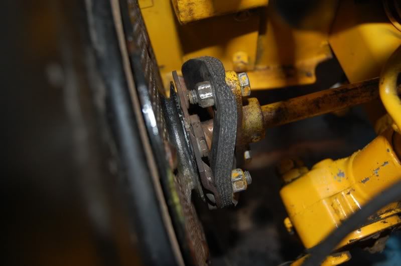 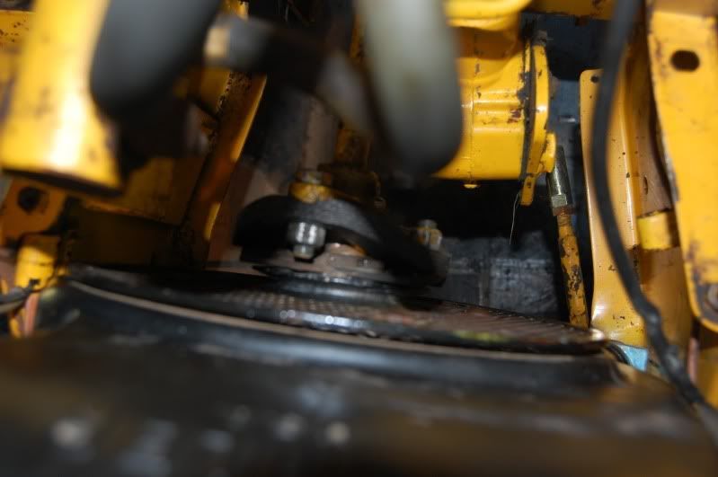 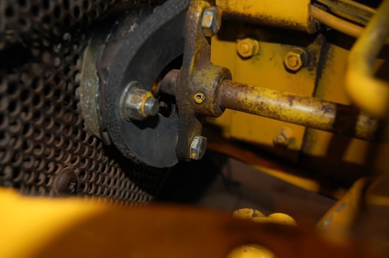 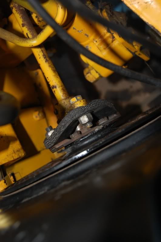 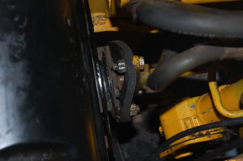 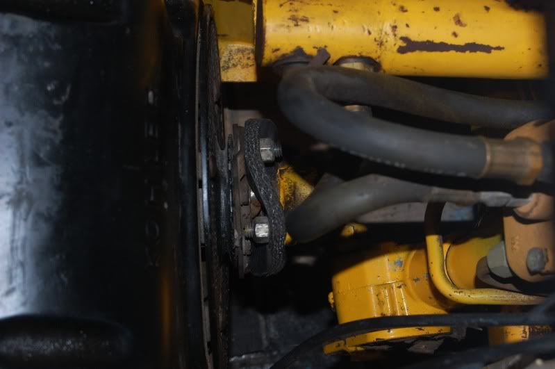
|
|
#3
06-03-2010, 09:56 PM
|
|||
|
|||
|
Pic number 3 shows that the shaft is NOT inside the bushing. Take it apart and insert the shaft in the bushing.
Also turn your shaft coupler bolt around so that all the nuts are exposed. Scott |
|
#4
06-03-2010, 09:58 PM
|
|||
|
|||
|
Geeezzzz for that matter every pic shows it not inside the bushing!
I'm not sure what you did to accomplish that...tip the motor forward? force the trans in place?...at any rate as it sits your shaft is about 1/2 too long to the pump and it's putting a lot of unnecessary force on the imput shaft of the pump. Do not run it this way. Further, the correct way to install a shaft in my opinion and in the opinion of the manual is to remove the pins and install the shaft lose and then repin after everything is lined up.....yeah I know...... Scott |
|
#5
06-03-2010, 10:12 PM
|
||||
|
||||
|
Good eyes. I didn't see that the first time...I didn't know you could actually get it bolted together like that. That probably isn't possible in anything other than a QL because it the engine mounts give a bit and let the engine tip forward enough.
|
|
#6
06-03-2010, 11:10 PM
|
||||
|
||||
|
I ran into a similar situation swapping a K301 from a 1250 into my 682 that was previously equipped with a KT17. The original 682 shaft was too short, and wouldn't come close to being inside the bushing. Remedied it with a new, longer drive shaft I made from 5/8" rod, and 2 rubber discs instead of 1...also on the 82 series iso mount and raised engine mount assembly, the holes to mount the engine are slotted a bit to allow for proper alignment...not sure if they are the same on your 14/1650.
Good luck Jeff (teet)
__________________
CCC 1211 71 127  102 122 1962 Original |
|
#7
06-04-2010, 08:23 AM
|
||||
|
||||
|
Quote:
So...I should take the rag joints off on both sides, reinstall the engine side (finger tight I assume), and then install the transmission side? |
|
#8
06-04-2010, 08:33 AM
|
||||
|
||||
|
As long as the rear of the driveshaft is seated properly, just unbolt the engine, slide it forward, and then slide it back, and make sure the driveshaft winds up inside the spherical ball bushing instead of jammed up against it.
|
|
#9
06-04-2010, 09:41 AM
|
|||
|
|||
|
I agree with Matt. I do not agree with Scott on how to properly install a driveshaft. I can't see how beating on the driveshaft while in the tractor is a good thing on the components, when it's pretty much just as easy to do it without beating on anything.
AJ
__________________
1980 [COLOR="Red"][/COLOR]482- Stock 1981 [COLOR="Red"][/COLOR]582- Mag18, Sleeve Hitch, Spring assist 1979 [COLOR="Red"][/COLOR]682- Mag18, Sleeve Hitch, Spring Assist, #1 Tiller 1980 [COLOR="Red"][/COLOR]782- Mag18, Sleeve Hitch 1983 [COLOR="Red"][/COLOR]982- Stock, Fully Optioned |
|
#10
06-04-2010, 10:45 AM
|
||||
|
||||
|
Quote:
1. Mounted it to the modified cradle 2. Tipped the engine in, and 'aligned' the drive shaft 3. Put in the rag joint and finger tightened the bolts 4. Installed ISO mounts and finger tightened them 5. Went around and tigtened all of the ISO mounts to the frame 6. Tightened up front and rear rag joint bolts Are you saying that I should have installed the cradle and then put in the engine? How do I gurantee that the holes will line up? |
|
|
|
Cub Cadet is a premium line of outdoor power equipment, established in 1961 as part of International Harvester. During the 1960s, IH initiated an entirely new line of lawn and garden equipment aimed at the owners rural homes with large yards and private gardens. There were a wide variety of Cub Cadet branded and after-market attachments available; including mowers, blades, snow blowers, front loaders, plows, carts, etc. Cub Cadet advertising at that time harped on their thorough testing by "boys - acknowledged by many as the world's worst destructive force!". Cub Cadets became known for their dependability and rugged construction.
MTD Products, Inc. of Cleveland, Ohio purchased the Cub Cadet brand from International Harvester in 1981. Cub Cadet was held as a wholly owned subsidiary for many years following this acquisition, which allowed them to operate independently. Recently, MTD has taken a more aggressive role and integrated Cub Cadet into its other lines of power equipment.
This website and forum are not affiliated with or sponsored by MTD Products Inc, which owns the CUB CADET trademarks. It is not an official MTD Products Inc, website, and MTD Products Inc, is not responsible for any of its content. The official MTD Products Inc, website can be found at: http://www.mtdproducts.com. The information and opinions expressed on this website are the responsibility of the website's owner and/or it's members, and do not represent the opinions of MTD Products Inc. IH, INTERNATIONAL HARVESTER are registered trademark of CNH America LLC
All material, images, and graphics from this site are the property of www.onlycubcadets.net. Any unauthorized use, reproductions, or duplications are prohibited unless solely expressed in writing.
Cub Cadet, Cub, Cadet, IH, MTD, Parts, Tractors, Tractor, International Harvester, Lawn, Garden, Lawn Mower, Kohler, garden tractor equipment, lawn garden tractors, antique garden tractors, garden tractor, PTO, parts, online, Original, 70, 71, 72, 73, 76, SO76, 80, 81, 86, 100, 102, 104, 105, 106, 107, 108,109, 122, 123, 124, 125, 126, 127, 128, 129, 147, 149, 169, 182, 282, 382, 482, 580, 582, 582 Special, 680, 682, 782, 782D, 784, 800, 805, 882, 982, 984, 986, 1000, 1015, 1100, 1105, 1110, 1200, 1250, 1282, 1450, 1512, 1604, 1605, 1606, 1610, 1615, 1620, 1650, 1710, 1711, 1712, 1806, 1810, 1811, 1812, 1912, 1914.


 Linear Mode

